Cassells' Carpentry and Joinery/Hand Tools and Appliances
Carpentry and Joinery
HAND TOOLS AND APPLIANCES.
Introduction.
The reader of this book is assumed to have some acquaintance with woodworking, and not to stand in need of detail instruction as to the shape, action, care and use of each and all of a woodworker's tools. This information is given in comprehensive style in a companion volume, entitled "Woodworking," produced by the Editor of this present book, and sold by the same publishers at 9s. Should any reader of this chapter desire further particulars of the tools and appliances here briefly mentioned, he is recommended to consult that work, which undoubtedly contains the most complete description of woodworking tools yet published.
Classification of Tools.
Tools may be classed according to their functions and modes of action, as follows: (1) Geometrical tools for laying off and testing work—such tools are rules, straight-edges, gauges, etc. (2) Tools for supporting and holding work; such tools are benches, vices, stools, etc. (3) Paring or shaving tools, such as chisels, spokeshaves, planes, etc. (4) Saws. (5) Percussion or impelling tools, such as hammers, mallets, screw-drivers, and (combined with cutting) hatchets, axes, adzes, etc. (6) Boring tools, such as gimlets, brace-bits, etc. (7) Abrading and scraping tools, such as rasps, scrapers, glasspaper, and implements such as whetstones, etc., for sharpening edged tools.
Geometrical Tools.
Straight-edge.—Mechanics in the building trades use a straight-edge, usually made to the shape shown by Fig. 3, and not larger than 15 ft. long, 6 in. wide, and 1¼ in. thick, made from a pine board cut from a straight-grown tree. All straight-edges should be tested occasionally.
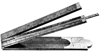
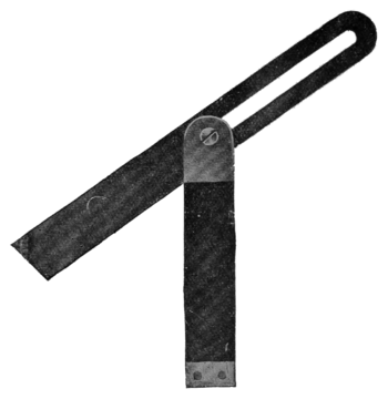
Squares and Bevels.—These are used for setting out and testing work. The joiner's steel square is a mere right angle of steel, sometimes nickel-plated, graduated in inches, ¼ in. and in., or otherwise as required. The try square (Fig. 4) has a rosewood or ebony stock. The tool shown by Fig. 5 is also of use in setting out and testing mitres, but the proper mitre square is shown by Fig. 6. Try squares are also made with iron frames which are channelled and perforated to reduce weight. Adjustable squares with graduated blades are useful in putting fittings on doors and windows. By means of the sliding bevel (Fig. 7) angles are set off in duplicate; the set screw secures the blade at any desired angle with the stock. A crenellated square has a blade which is notched at every principal graduation, and is used chiefly for setting out mortises and tenons.
Marking Work for Sawing.—The chalk line is used for long pieces of timber, the pencil and rule for ordinary applications, and the scribe for particular work. The "chalk line" is a piece of fine cord rubbed with chalk or black pigment, and strained taut. To mark the work the chalk line is lifted vertically and near the centre, and when released makes a fine and perfectly straight line upon the work. Coloured chalks and pigments are also used.
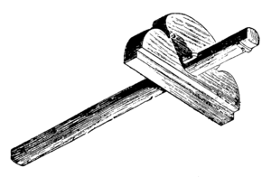
Marking and Cutting Gauges.—Ordinarily the carpenter draws a line close to and parallel to the edge of a board by means of a rule held in one hand, with the forefinger against the edge of the work and the pencil held close against the end of the rule; but the marking gauge (Fig. 8) gives more accurate results. The gauge may have a pencil point instead of the steel point shown. Developments are the mortise gauge (Fig. 9) and the cutting gauge (Fig. 10), having either a square or oval sliding stock or head. The panel gauge (Fig. 11) is used to mark a line parallel to the true edge of a panel or of any piece of wood too wide for the ordinary gauge to take in.
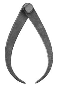
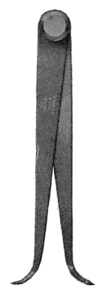
Compasses, Dividers, and Callipers.—Ordinary wing compasses (Fig. 12) are generally used, but for particular work instruments with fine or sensitive adjustments are obtainable. Spring dividers (Fig. 13) are used for stepping off a number of equal distances, for transferring measurements and for scribing. Callipers (Figs. 14 and 15), obtainable in many styles, are used for measuring diameters of cylindrical solids and recesses.
Shooting Boards.—The shooting board (Fig. 16) is used for trueing up with a plane the edges of square stuff. That shown is the simplest possible, but other and improved shapes are obtainable.
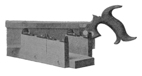
Appliances for Mitreing.—The simplest appliance used in cutting mitres is the ordinary mitre block, the work being laid upon a rebate, and saw kerfs in the upper block serving as a guide for the tenon saw. Inclined and other varieties of mitre blocks are in use. The mitre box (Fig. 17) is generally used for broader mouldings. The mitre shooting block (Fig. 18) is used for shooting or planing the mitred ends of stuff previously sawn in the mitre block or box; in the illustration the rebate or bed for the work is cut out of the solid, but it is general to build up the block with three thicknesses of stuff, and so avoid cutting a rebate. The donkey's-ear shooting block (Fig. 19) is used for mitreing or bevelling the edges of wide but thin material with the cut at right angles to that adopted for stouter mouldings; another form of this block (Fig. 20) has a rest a for the material, A bed B for the shooting plane, a guide C for the plane, and a frame D which is fixed in the bench screw or to the tail of the bench. The mitre template (Fig. 21) is another aid to cutting mitres. Its use will be explained on a later page.
Spirit Levels.—The spirit level is used for determining the planes of the horizon—that is, the plane forming a right angle to the vertical plane. A frame firmly holds a closed glass tube nearly filled with anhydrous ether, or with a mixture of ether and alcohol (see Fig. 22). Good spirit levels have a graduated scale engraved on the glass tube or on a metal rule fastened to the frame beside it. There are many varieties of spirit levels, but all are made on the same principle.
Plumb Rule and Square.—The plumb rule (Fig. 23) is used by the carpenter and fixer for testing the vertical position of pieces of timber, framing, doorposts, sash frames, etc., which should be fixed upright. The plumb square (Fig. 24) is useful for testing the squareness of work and at the same time the levelness of a head, it being for this purpose sometimes more useful than a spirit level.
Tools for Supporting and Holding Work.
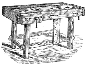
A bench with side and tail vices is illustrated at Fig. 27, and, although not much used by joiners, is a very useful form for small work or as a portable bench. The top and tail vice cheeks contain holes for the reception of bench stops of iron or wood, against which, or between which, work is held for framing, etc.
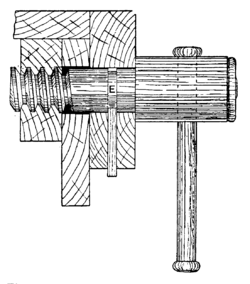
Bench Screws.—A common form of joiner's bench screw is shown by Fig. 28, inside and sectional views being shown respectively by Figs. 29 and 30. D is the side or cheek of the bench to which a wooden nut (A) is screwed. The box B, which accurately fits the runner shown inside it, is fixed to the top rail connecting the legs, and to the top and side of the bench. Care is taken to keep the runner at right angles to the vice cheeks. To fasten the vice outer cheek and screw together, so that upon turning the latter the former will follow it, a groove E is cut. Then from the under edge of the cheek a mortise is made, and a hardwood key is driven to fit fairly tight into the mortise, its end entering E. The screw cheek is usually about 1 ft. 9 in. long, 9 in. wide, and 2 in. to 3 in. thick. The runner is about 3 in. by 3 in. and 2 ft. long. The wooden screws and nuts can be bought ready made.
Bench screws are known in great variety, and include an instantaneous grip vice (Fig. 31), a most useful appliance.


An improved form of this is shown at Figs. 33 and 34. A block is screwed to the stop, and to this the nut of an ordinary shutter bolt is fixed. A slot is cut in the cheek of the bench, as shown. The shoulder of the bolt works against a large washer. This stop can readily be raised or lowered. Two or three steel nails driven in near the top of the stop and filed to form teeth can be used to hold the work. A very useful stop may be contrived, as shown by Fig. 35, by filing one end of a back flap hinge so as to form teeth, the other flap being screwed down to the bench. A long screw through the middle hole in the loose flap affords means of adjustment. By loosening this long screw, the front edge of the stop may be raised,

but to retain it in its position it should be packed up with a piece of wood, and the screw tightened down again. A plain iron stop with a side spring to keep it at any desired height is shown by Fig. 36. This form of stop fits into holes mortised through the bench top. Figs. 37 and 38 show good forms of adjustable bench stops that are obtainable from tool-dealers; their principle is fairly obvious on reference to the illustrations.
Sawing Stools or Trestles.—The three-leg sawing stool is of but little service and almost useless for supporting work in course of sawing. Probably one of the best forms of this useful appliance is the four-legged stool shown by Fig. 39. This needs to be built substantially.
Cramps.—A hold-fast for temporarily securing work to the bench is shown by Fig. 40.


used for driving into the ends of boards which have been jointed and glued, to pull together the joint, and for similar purposes by the joiner. They are also used for drawing together face joints when glued, but only in cases where the holes made by the dogs are to be covered afterwards by another piece of lining. A stronger form is also sometimes used by the carpenter for common flooring. The dog is driven into the joist firmly, there being enough space between the dog and the edge of the floor-board to admit a pair of folding wedges, which are then driven tight home, and the floorboards nailed down before removing the dog. More suitable cramps for this purpose are those usually known as floor cramps or dogs, illustrations and particulars of which


will be found in the section on floors. Cramps and similar appliances in less general use, but of importance in special cases, will be illustrated and their use explained, in each of the particular sections to which they belong. For cramping circular work there are many special devices, the flexible steel cramp (Fig. 49) being typical of them. The flexible cramp is shown in use, tightening up

the four joints used in the construction of a circular seat or other piece of work.
Pincers.—These are used for extracting and beheading nails, and in cases where a form of hand vice is wanted for momentary use. Two chief patterns are available, Fig. 50 showing the Lancashire pattern.

Tower pincers have a round knob in place of the cone on the end of the handle.
Paring and Shaving Tools.
Chisels.—For full information as to the action of these tools readers are referred to "Woodworking," the companion volume already alluded to. Firmer chisels shown by Fig. 51 range from 1/8 in. to 11/8 in. in width, and their use is to cut away superfluous wood in thin chips. The ordinary kind is strong and is made of solid steel, and is used with the aid of a mallet. A lighter form made with bevelled edges (Fig. 52) is used, generally without a mallet, for fine work and for cutting dovetailed mortises. For paring, a longer chisel is generally employed (Fig. 53). Mortise chisels (Fig. 54) have various shapes, according to their particular uses, and require to be strongly made.

Draw Knife.—The draw knife (Fig. 56) is used for roughing stuff to shape preparatory to working with finer tools.
Spokeshaves.—An ordinary spokeshave is merely a knife edge in a suitable holder (Fig. 57); it may jump if the iron is loose, or if the back part of the iron touches the work before the cutting edge. Spokeshaves are best made with iron stocks and with screws to regulate the cutting iron (Fig. 58).
Planes.—These are the tools chiefly used for smoothing work which has been sawn to approximate size. The simplest plane is a chisel firmly fixed into a wooden block. The construction of an ordinary plane is shown in the sectional view (Fig. 59),

in which A shows the stock; B, the wedge; C, cutting iron; D, back iron ; F, screw and nut for fastening the cutting and back irons together; the mouth through which the shavings pass upwards is shown. The jack plane (Fig. 60)

is the first plane applied to the sawn wood; its parts are: the stock, 17 in. long; the toat, or handle; the wedge; the cutting iron, or cutter, about 2⅛ in. wide; and the back iron. The trying or trueing plane (Fig. 61)

is of similar construction, but is much longer, so as to produce truer surfaces. A still longer trying plane called the jointer is used for jointing boards in long lengths; since the introduction of machinery it is seldom used. The smoothing plane (Fig. 62) smooths the work to form a finished surface ; for pine or other soft woods it is 9 in. long, and its iron is 2¼ in. wide on the cutting face. Some smoothing planes have iron fronts, as shown in the sectional view, Fig. 63; these can be adjusted for the finest shaving desired. A good form of iron smoothing plane is shown by Fig. 64; this is intended for superior work. The rebate plane (Fig. 65) is without a back iron, and its cutting iron extends the full width

Fig. 62.—Smoothing Plane.
of the tool, thus enabling the angles of rebates to be cleaned up. Other varieties of planes include the bead plane (Figs. 66 to 68), used for working single and return beads and round rods. Hollows, rounds, etc. (Figs. 69 to 73), are used for working

Fig. 63.—Iron Mouth-piece for Smoothing Plane.
straight mouldings of all kinds, but machinery has of late years been increasingly used for such work. Small planes of varying shapes are used for forming mouldings on circular work. The compass plane, used for forming the face of concave ribs, etc., was formerly made of beech wood. The one generally used at the present time is made of steel entirely. The sole of the plane is about 10 in. long, 2¼ in. wide,

Fig. 64.—Iron Smoothing Plane.
and 1/32 in. thick. It is adjusted by means of a screw, and with it both concave and convex surfaces may be worked perfectly

Fig. 65.—Rebate Plane.
true and even. There are also employed ovolo lamb's-tongue planes for forming the mouldings on sash stiles and

Figs. 66, 67, and 68.—Bead Plane.
rails. The sash fillister (Fig. 74) is generally used for making rebates adjacent to the back side of the stuff, its fence working against the face side. When rebates have to be made next to the face side of the work a side fillister (Fig. 75) is most useful; its fence is adjustable to the face, allowing a rebate to be made of any width within the breadth of the plane iron. These planes,

and also the plough (Fig. 76), are principally used for grooving with the grain. They are not used so much as formerly, owing to the introduction of machinery in large

shops, but they are still indispensable to most joiners. For the working of hardwoods, to obtain perfect joints, gun-metal or iron planes known as the shoulder plane and bullnose plane are considered indispensable, as is also the steel smoothing

plane which is used for cleaning up face work. The router, or "old woman’s tooth" (Fig. 77), is used for working out the bottoms of rectangular cavities; the chariot plane (almost obsolete), is used for the small parts of work which the smoothing

plane cannot get at, and for planing end grain and cross-grain work ; chamfer planes are used for taking off sharp edges to form chamfers; mitre shooting planes

are sufficiently described by their name; and the plough or plough plane (Fig. 76), used for cutting or "ploughing" grooves. There are many other varieties of planes; the names and uses of the more important

will be treated upon in some of the following sections. Particulars of these may be found readily by reference to the index.
Hand Saws.
The saw cannot be classified with any other tool. It is essentially a tool for use across the fibre of the wood, and the separation is a cutting, not a tearing action, as fully explained in the work already alluded to. The carpenter and joiner has some six or

Fig. 78.— Hand Saw.

Fig. 79.— Tenon Saw.
eight saws, comprising the rip, cross-cut, hand, panel, tenon, dovetail, bow or turning, and keyhole. The hand-saw type includes the hand saw proper, the ripping, half-ripping, and panel saws, all of similar outline, but differing in dimensions and in form and size of teeth. There is no sharp distinction between these tools, as they merge one into the other; yet at the extremes it would be impossible to substitute the ripping and panel saws one for the other. The hand saw, however, which is a kind of compromise between extremes, is used indiscriminately for all purposes,

Fig. 80. — Bow or Frame Saw.
especially by the carpenter. Fig. 78 is a saw with nibbed back. Straight back and skew back or round back saws are made, and the teeth of the latter do not require to be set. The typical hand saw has a blade which is from 24 in. to 28 in. long. Its blade is as thin as possible, consistent with sufficient strength to prevent the saw buckling under thrust; the taper of the blade is calculated to withstand the thrusting stress without unduly increasing the mass of metal. The teeth are bent to right and left alternately — this being known as the set

Fig. 81. — Compass Saw. Fig. 82.— Pad Saw.
— and their outline is angular. The teeth are so sharpened that their outer points enter the wood first, the fibre being divided by a gradually incisive kind of action. Six teeth to the inch are suitable for a hand saw used for cutting rough stuff, trimming joists, cutting rafters, etc. For joiners' work the panel saw, 2 in. or 3 in. shorter and much narrower, thinner, and lighter than the hand saw, is preferable. The rip saw has a blade about 28 in. long, and its teeth, three to the inch, are sharpened square across the blade and set very much forward; this saw is used for cutting along the grain, known as ripping. The tenon saw (Fig. 79) is used for cutting shoulders and in all cases where a clean cut is essential; it obtains this by means of its fine teeth. The dovetail saw is a small tenon saw, it being 6 in. or 8 in. long, whereas the ordinary tenon saw is 12 in. or 14 in. long.
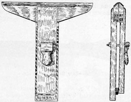
Figs. 83 and 84. — Improved Saw Vice.
The bow saw, known also as the turning saw or frame saw (Fig. 80), cuts out curved work with or across the grain, the compass, turning, or lock saw (Fig. 81) being used for a similar purpose, and in cases where a large saw could not be employed. A keyhole or pad saw (Fig. 82) is used for small internal curved work.
Appliances for Sharpening Saws.—For holding a hand saw during the process of sharpening, a saw vice (Figs. 83 and 84) is used, there being many designs to choose from. For sharpening English hand saws, the triangular file (Fig. 85) is commonly

Fig. 85.— Triangular Saw File.
used; its size varies with that of the saw for which it is required. Special shapes of files are necessary for sharpening American cross-cut and rip saws. Saw files are made in three degrees of fineness. For levelling down or topping saw teeth preparatory to sharpening, a flat file is necessary. The angles of saw teeth are set off with a protractor or hinged rule. For setting the teeth after they have been sharpened—that is, to bend each alternate tooth to one side—saw sets (Fig. 86) are used, or instead, patent contrivances are brought into requisition, these being so arranged that all the teeth can readily be set to one line. A useful form of plier saw set is shown by Fig. 87, and the method of

Fig. 86.—Saw Set with Gauge.
using it by Fig. 88. The amount of set can be regulated by the adjusting screw A. For hammer setting, however, a setting iron with bevelled edges is secured in the vice, the saw laid flat upon it, and the teeth struck one at a time with the pene of a small hammer (Fig. 89). This is the most satisfactory method of setting saw teeth when the operator has the necessary skill.
Tools of Percussion and Impulsion.
Hammers.—The carpenter and joiner has the choice between two or three shapes of hammer head. There is the Exeter or London pattern (Fig. 90), the Warrington

Fig.87—Plier Saw Set.
(Fig. 91), and the adze-eye claw pattern (Fig. 92), the last named being less used

Fig. 88.—Method of using Plier Saw Set.
than the others in the workshop, but being very convenient for many kinds of handiwork.
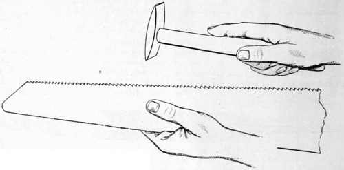
Fig. 89.—Hammer Setting Saw Teeth.
The hammer heads are of iron, with steel faces and penes. Two hammers, one weighing from 1 lb. to 1½ lbs., and the other from ½ lb. to ¾ lb., will be found useful, and it should be remembered that a heavy hammer applied lightly and skilfully leaves fewer marks and does less damage than a light hammer applied with great force.

Fig. 90.—Exeter or London Hammer.

Fig. 91.—Warrington Hammer.

Fig. 92.—Adze-eye Claw Hammer.
Mallets.—These are used for driving wood chisels, for knocking light framing together, and in cases where a hammer would probably damage both tools and

Fig. 93.—English Mallet.
material. An English beech mallet is shown by Fig. 93, but the American hickory or lignum vitæ pattern is perhaps more convenient, it having all the sharp edges chamfered off and the handle being round and easier to grasp. In some American mallets the handle screws into the head.
Axes, Hatchets, and Adzes.—These are both percussion and cutting tools, as they combine the offices of the hammer and chisel. Axes have long handles, and may be slung as sledge-hammers, and they have heads more or less of the shape shown by Fig. 94, which illustrates the Kent pattern, many other patterns, however, being in use. Hatchets have short handles, and
 |
 |
| Fig. 94.—Kent Axe Head. | Fig. 95.—American Axe Head. |
are used with one hand. The Kent pattern already illustrated is common, as is also the Canadian or American pattern shown by Fig. 95. The adze has a long, curved handle, and the operator stands with one foot upon the wood in the line of the fibre, and thus assists in steadying the work. The variety in the shape of the adze heads is very great, but it is sufficient here to show the Scotch pattern (Fig. 96).
Screwdrivers.—These are tools of impulsion, and at least two or three will be required—long and short, and with wide and narrow blade. For general work, a tool of medium length should be obtained, although there are, on the one hand, enthusiastic advocates of a short tool, and on the other hand of a long tool for each and every purpose. Any advantage gained by a short over a long tool, or the reverse, is one of advantage in special circumstances only, and not one of saved energy; theoretically,

Fig. 96.—Scotch Adze Head.
the length does not enter into consideration at all, except when, in starting to extract a difficult screw, the driver is tilted from the upright; but this is at the risk of a broken tool edge and defaced screw-head. The worker then must decide for himself as to which sizes will best suit his purposes. London screwdrivers have a plain handle (Fig. 97) or oval handle; cabinet screwdrivers are lighter tools, and there is, indeed, a great variety of patterns from which the worker can choose the tools that suit him. The gimlet-handle screwdriver has certain proved advantages; and the brace screwdriver—a screwdriver bit used in an ordinary brace—is useful for driving good-sized screws easily and quickly. Short screwdrivers are used in screwing on drawer locks, there being a much heavier though just as short a tool used for screwing up plane irons. Automatic screwdrivers (Fig. 98) were introduced from America, and by their means the screw is driven home merely by pressure on the top of the handle.
Boring Tools.
Bradawls.—These have round stems and chisel edges (Fig. 99); thus the edge cuts the fibres of the wood and the wedge-like form of the tool pushes them aside. Its special use is for making comparatively
 |
 |
| Fig. 97.—Plain Handle London Screwdriver. | Fig. 98.—Miller's Falls Automatic Screwdriver. |
small holes in soft wood, and the principal limitation of the tool is that there is no provision for the waste material.
Gimlets.—These are made in many forms, the best known being the twist (Fig. 100) and the shell (Fig. 101), lesser known shapes being the twist-nose (Fig. 102) and the auger (Fig. 103). Gimlets will bore end grain as well as across the fibres, but there is a risk, in boring a narrow strip, of the pointed screw splitting the wood.
Brace and Bits.—There are various kinds of braces on the market, but the more generally used are the two following: A wooden brace with brass mountings is shown at Fig. 104. It is better to buy the bits fitted to this brace, as they are more truly centred than those bought separate are likely to be, and the centering of the bits is essential to their proper action. With the American pattern brace (Fig. 105) this is not necessary, as by turning the socket

Fig. 99.—Bradawl.

Fig. 100.—Twist Gimlet.

Fig. 101.—Shell Gimlet.

Fig. 102.—Twist-nose Gimlet.

Fig. 103.—Auger Gimlet.
the jaws are expanded or contracted so as to grip the shank of any size bit. This kind of brace may be had with a ratchet movement, which is very useful for boring or turning screws in corner positions where a complete revolution is not possible. Bits are known in very numerous forms. The pin bit is like a gouge sharpened both inside and outside; when its corners are removed, it becomes a shell bit suited for boring at right angles to the fibre of the wood. The spoon bit resembles the shell bit, but is pointed; it is found to work easily, freely, and well. The nose bit is of similar shape, but its cutting edge is a part of the steel bent nearly to a right-angle and sharpened to form a kind of chisel; this tool is efficient for boring the end way of the grain, but not across the grain. The twist-nose bit or half-twist, or Norwegian bit, is exactly of the shape shown for the twist-nose gimlet by Fig. 102; it screws itself into the wood, and the chips tend to rise out of the hole. It is found to split narrow strips of wood, but it answers well for all other purposes. All the above bits can be obtained in a great variety of sizes; but exact size is not guaranteed by the dealers, and the best plan is to bore a hole and measure, rather
 |
 |
| Fig. 104.—Wooden Brace. | Fig. 105.—Steel Brace. |
than measure the bit. Holes are enlarged by means of a hollow taper bit. Patent twist bits (Fig. 106) having a screw centre are known as screw bits, and these bore well in any wood and in any direction, relieving themselves of the chips and cutting

Fig. 106.—Gedge's Twist Screw Bit.
true to dimensions. Centre bits are perhaps the most commonly used bits (see Figs. 107 and 108); they are useful for boring large holes, and are much superior to shell type bits in the important point of boring exactly where the hole is required. Expanding centre bits (Fig. 109) are known, and are a great convenience if of good quality. The Forstner auger bit (Fig. 110) is guided by its periphery instead of its centre, and consequently it will bore any arc of a circle, and can be guided in any

Fig. 107.—Centre Bit with Pin.

Fig. 108.—Centre Bit with Screw.

Fig. 109.—Anderson's Expanding Bit.

Fig. 110.—Forstner Auger Bit.

Fig. 111.—Auger.
direction regardless of grain or knots, leaving a true, polished, cylindrical hollow.
Augers.—The auger (Fig. 111) bores well in the direction of the grain of the wood, and is complete in itself. It is a steel rod, having a round eye at one end, through which a round wooden handle passes. At the other end is a spiral twist terminating in a conical screw with a sharp point. The edge of the spiral is a nicker which cuts the grain of the wood around the edge of the hollow.

Fig. 112.—Handled Steel Scraper.
Abrading and Scraping Tools.
Steel Scrapers.—The scraper is a thin and very hard steel plate, approximately 5 in. by 3 in., with or without a handle (see Fig. 112). Its action is really that of a cutting tool. It is used on a surface previously

Fig. 113.—Action of Steel Scraper.
made as smooth and level as the plane can make it. The scraper is so sharpened that a burr or feather is formed along its edges (see the diagram, Fig. 113). The thickness of the scraper blade, which is about in., is shown exaggerated. The edge is filed straight and flat, it is then rubbed along the oilstone to remove file marks, and finally the edge is turned and sharpened by two heavy rubs with a round steel burnisher held at an angle of about 30° with the plate.
Glasspaper.—This is the chief abrading material used in woodworking, and consists of strong paper coated with powdered glass secured to the paper with glue. The different

Fig. 114.—Glasspaper Rubber.
grades of glasspaper are numbered from 3 to 0, and even finer. For properly using glasspaper a rubber (Fig. 114) is required, this being a shaped wooden block faced with cork. In use the glasspaper is folded round it. Glasspaper has entirely replaced the old-fashioned sandpaper, which was a similar material, except that fine, sharp sand was used instead of powdered glass.
Rasps and Files.—Woodworkers' rasps are generally half-round, though sometimes flat. The wood rasp (Fig. 115) is coarser than the cabinet rasp. The ordinary half-round wood file (bastard cut) is shown at Fig. 116. Both range from 4 in. to 14 in. in length. The usual files used for keeping saws in order chiefly are known as triangular taper (Fig. 85), and have already been alluded to.

Fig. 115.—Half-round Wood Rasp.

Fig. 116.—Half-round Wood File.
Grindstones.—The grindstone (Fig. 117), many varieties of which are obtainable, is an appliance for removing a superfluous thickness of metal, not for producing a good edge. It should be of a light grey colour, even throughout.
Oilstones.—On an oilstone the joiner sharpens his tools, which have been previously ground to shape on the grindstone. The oilstones in most general use are four in number—the Charnley Forest, Turkey, Washita, and Arkansas. The Charnley Forest is of a greenish-slate colour, and sometimes has small red or brown spots—the lighter the colour the better; it may take a little more rubbing than other stones to get an edge on the tool, but that edge will be keen and fine. Some Turkey oilstones are of a dark slate colour when oiled, with white veining and sometimes white spots; they give a keen edge, but wear unevenly, and also are very brittle; they are notoriously slow-cutting, and are expensive. The cheapest oilstone at first cost is the Nova

Fig. 117.—Treadle Grindstone on Iron Stand.

Fig. 118.—Oilstone in Plain Case.
stone of various sizes and shapes are required for gouges, router cutters, etc. It is usual to keep an oilstone in a box or case (Fig. 118). Neat's-foot oil or sperm oil commonly is considered best for oilstone use; lard oil containing sufficient paraffin to prevent it going thick in cold weather is also recommended. Many other oils are used for the purpose, but all tend to harden the surface of the stone much more quickly than neat's-foot or sperm. The oil can be kept in a bench oil-can, which will come in generally useful.
Emery Oilstones and Oilstone Substitutes.—Emery oilstones are an American introduction, and are made of Turkish emery, one face being of fine and the other of medium coarse material. They have the advantage over any natural oilstone of being uniform in texture, and of not being brittle. Oilstone substitutes are strips of zinc upon which is sprinkled a little flour emery and oil, this working more quickly than a proper stone, but not giving so finished an edge.
Nails, Screws, and Glue.
Nails.—Nails may be of iron, steel, etc., wrought, cast, cut, or made of wire. Formerly nails were said to be 6-lb., 8-lb., etc., according as 1,000 of the variety weighed that amount—hence now such meaningless terms as sixpenny, eightpenny, and tenpenny nails, in which "penny" is a corruption of "pound." Of the nails commonly used in carpentry and joinery, the cut clasp nail, machine-made from sheet "iron" (probably steel), may be used for almost any purpose, and is not liable to split the work. Rose-head nails have a shank parallel in width, but tapered to a chisel point in thickness; these are made of tough wrought iron, and are used chiefly for field-gates and fencing. Wrought clasp nails resemble the cut clasp, but have sharper points, and are used chiefly in common ledged doors, as they will readily clinch. Oval steel nails are nicely shaped, very tough, and are less likely to split the material than any other kind of nail; slight shallow grooves in the shank increase the holding power. Brads are known in more than one variety. The cut-steel large brad is used in flooring, and does not make such a large hole as a cut nail. The cut-steel small brad is used for general purposes. French nails are of round wire, pointed, and have round, flat heads; they are strong, but their unsightly heads cause their use to be confined to rough work.

Fig. 119.—Square Nail Set or Punch.
The double-pointed nail is intended for dowelling and other purposes.
Nail Sets or Punches.—For punching nail heads below the surface of the work a steel set (Fig. 119) of square or round section is used.
Screws.—The screw nail commonly used for uniting woodwork is known as the wood screw, and, although it has been in use a long time, the present pointed screw was not made prior to the year 1841. The screw replaces nails in all fixing where the hammer cannot conveniently be used or where jarring must be avoided. The screw

Fig. 120.—Flat Head Wood Screw.

Fig. 121.—Round Head Wood Screw.

Fig. 122.—Cup Wood Screw.
possesses ten times the compression and attractive strength of ordinary nails, and, besides, is convenient for use in putting work together which is soon to be taken down. Screws are made in almost endless variety, but the best known three are: flat-head screw (Fig. 120), made of iron, steel, or brass; round-head screw (Fig. 121), which is generally japanned and used for fixing bolts, locks, etc.; cup screw (Fig. 122), the head of which fits into a cup (as illustrated) which is let into the work flush with the surface.
Glue, Glue-pots, and Glue-brushes.—Glue, size, and gelatine are varieties of the same substance, differing only in the quantity of moisture and of impurities which they contain. Gelatine-yielding substances employed in glue manufacture include skins of all animals, tendons, intestines, bladders, bones, hoofs, and horns. Glue is manufactured by boiling the animal matter and straining the product into coolers, where it thickens into a jelly, which is cut into sheets and dried in the open air on frames of wire netting. Glue should be of a bright brown or amber colour, free from specks or blotches, nearly transparent, and with but little taste or smell. It should be hard and moderately brittle, not readily affected by moisture in the atmosphere, and should break sharply, but if it shivers as easily as a piece of glass it is much too brittle, though at the same time it must not be tough and leathery. Roughly speaking, a glue which will absorb more water than another is preferable. Good glue does not give off an unpleasant smell after being prepared a few days. In the workshop, different kinds of glue-pots are used, according to the quantity required. The usual glue-pot has an outer and an inner vessel and is shown in section at Fig. 123. When glue is used in large quantities, and steam pipes are laid on for heating purposes, the glue is kept hot on a water bath heated by steam pipes. The joiner prepares glue by breaking it into small pieces, soaking these

Fig. 123.—Section through a Glue-pot.
in clean, cold water for several hours, and then boiling the resulting lumps of jelly—the superfluous water having been poured off—in a double-vessel glue-pot for an hour or two, or until the glue runs easily from the brush without breaking into drops. A glue-brush can be bought for a few pence, and its bristles should be comparatively short. A cane brush is preferred by many workers, this being made with a piece of rattan cane about 8 in. long, the flinty skin for an inch or so at one end being cut away, the end soaked in boiling water for a minute or two, and then hammered till the fibres are loosened; this brush lasts as long as there is any cane left from which to hammer out a fresh end.
Other Tools and Appliances.—Many other tools and appliances not in such general use will be illustrated and described in connection with the matter treated in some of the other sections (see index).

