which carry the wheels are turned. As the studs PP are not exactly in line with the plane passing through the center of the rim of the wheel, there is a slight tendency to jerk the steering handle round when

Fig. 10. Arrangement of Axles and Wheels.
a wheel drops into a hole in the pavement, but the leverage of B being very short, this tendency is so small as to be hardly noticeable.
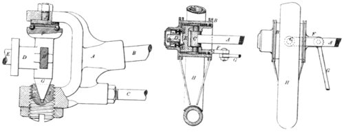
Fig. 10 illustrates the general principle upon which the front axle is designed, but the construction of the swivel joints P is far more elaborate, as can be seen from Fig. 11, which illustrates the actual design employed in the vehicles just described. Looking at Fig 9, it will be noticed that the front axle consists of two bars, one of which run
 | ||
| Fig. 11. Front Axle. | Fig. 11. Front Axle Wheels. | |
in a straight line from side to side, while the other is curved with the convex side upward. In Fig. 11 B is the end of the upper curved rod and C is the lower straight one. These two rods are secured into the casting A, which holds the part D upon which the wheel is carried, D being the part B at the left side of Fig. 10. The end E which is broken off in the drawing extends through the hub of the wheel and is provided with ball bearings so as to run without friction. The upper end F, of D, is arranged so as to be held by a ball bearing, as shown, against the end of J. By means of an adjusting screw I at the lower

