792
These pieces are to be riveted to the under- side of the fan-case. A fiber wheel 2 in. in diameter is turned in a lathe and fitted to a U-shaped piece of strap iron % in. wide. Now rivet the wheel-support to the under side of the fan-case in such a position that the wheel will support about one-half of the weight, the other half resting on the shoe.
The fan, Fig. 12, is cut out of sheet iron 1/32 in. thick. There are six blades, in pairs. The three pieces comprising the blades are to be firmly screwed to a brass hub, the dimensions of which are given. For added safety it is well to sweat the blades to the hub with solder to prevent them from becoming loose. The fan is secured to the shaft by means of one of the screws used to hold the blades to the hub, the screw being 1/16 in. longer than the others for this pur- pose.
The handle is about 1 in. in diame- ter and 2Y2 ft. long. Two pieces of strap iron are bent as shown and secured to the handle by means of two small bolts. On the under side of the handle a groove is cut to receive the
��Popular Science Monthly
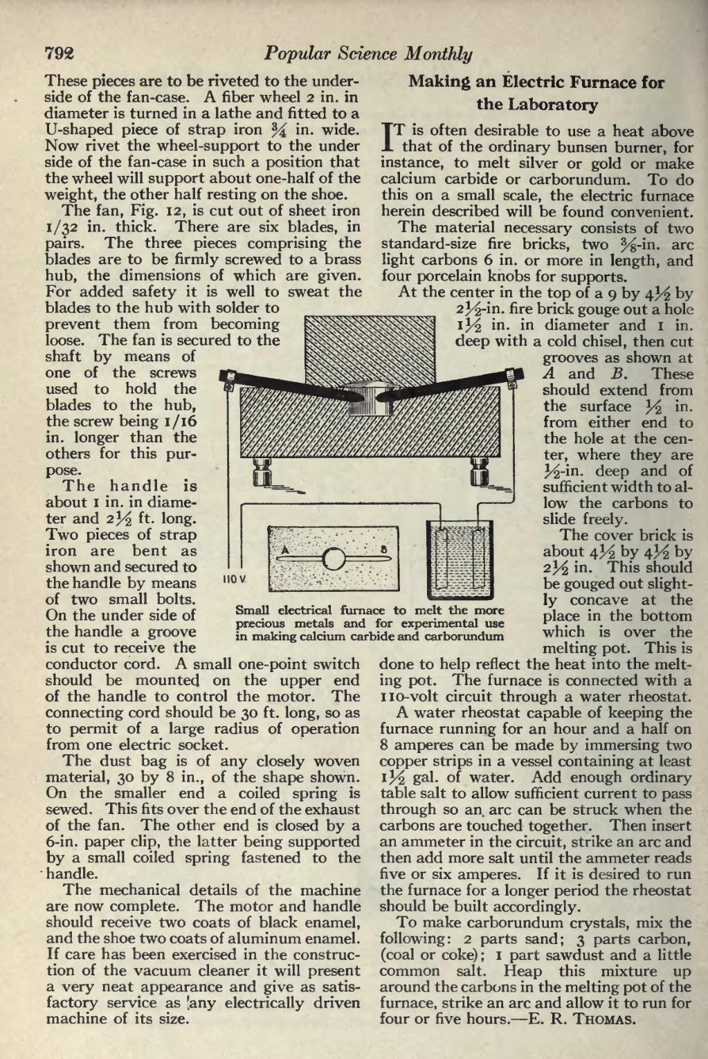
���Small electrical furnace to melt the more precious metals and for experimental use in making calcium carbide and carborundum
��conductor cord. A small one-point switch should be mounted on the upper end of the handle to control the motor. The connecting cord should be 30 ft. long, so as to permit of a large radius of operation from one electric socket.
The dust bag is of any closely woven material, 30 by 8 in., of the shape shown. On the smaller end a coiled spring is sewed. This fits over the end of the exhaust of the fan. The other end is closed by a 6-in. paper clip, the latter being supported by a small coiled spring fastened to the handle.
The mechanical details of the machine are now complete. The motor and handle should receive two coats of black enamel, and the shoe two coats of aluminum enamel. If care has been exercised in the construc- tion of the vacuum cleaner it will present a very neat appearance and give as satis- factory service as [any electrically driven machine of its size.
��Making an Electric Furnace for the Laboratory
IT is often desirable to use a heat above that of the ordinary bunsen burner, for instance, to melt silver or gold or make calcium carbide or carborundum. To do this on a small scale, the electric furnace herein described will be found convenient. The material necessary consists of two standard-size fire bricks, two %-'m. arc light carbons 6 in. or more in length, and four porcelain knobs for supports.
At the center in the top of a 9 by 4^ by 2^-in. fire brick gouge out a hole in diameter and 1 in. deep with a cold chisel, then cut grooves as shown at A and B. These should extend from the surface 3^ i n - from either end to the hole at the cen- ter, where they are 3^-in. deep and of sufficient width to al- low the carbons to slide freely.
The cover brick is about 4^ by 4^ by 2}/2 in. This should be gouged out slight- ly concave at the place in the bottom which is over the melting pot. This is done to help reflect the heat into the melt- ing pot. The furnace is connected with a no-volt circuit through a water rheostat. A water rheostat capable of keeping the furnace running for an hour and a half on 8 amperes can be made by immersing two copper strips in a vessel containing at least !/^2 gal- °f water. Add enough ordinary table salt to allow sufficient current to pass through so an arc can be struck when the carbons are touched together. Then insert an ammeter in the circuit, strike an arc and then add more salt until the ammeter reads five or six amperes. If it is desired to run the furnace for a longer period the rheostat should be built accordingly.
To make carborundum crystals, mix the following: 2 parts sand; 3 parts carbon, (coal or coke) ; 1 part sawdust and a little common salt. Heap this mixture up around the carbons in the melting pot of the furnace, strike an arc and allow it to run for four or five hours. — E. R. Thomas.
�� �
