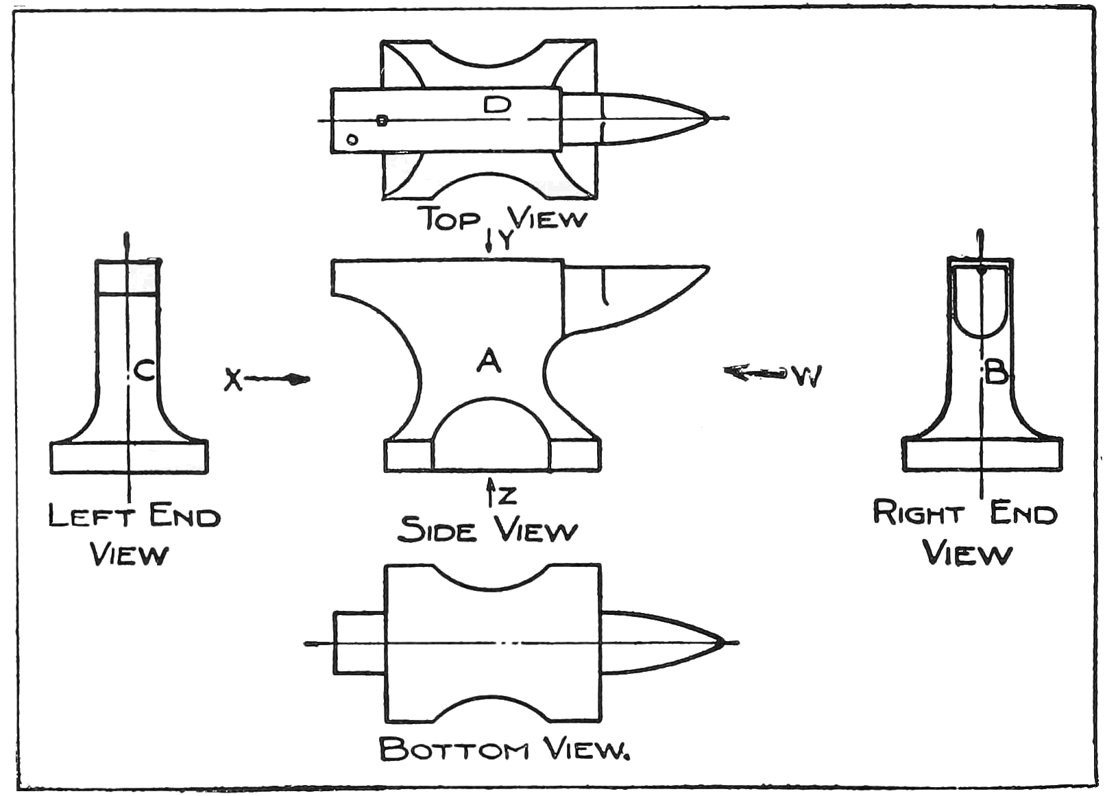
2. Orthographic Projection.—Before attempting to make any drawings, one must first get a clear idea of the way in which objects are represented in mechanical or orthographic drawings. If a person is going to make a photograph of an object, he nearly always makes a view taken from one corner so as to show as many sides as possible in order to give a complete idea of the object in one picture. For example, Fig. 1 shows how an anvil would be represented in a single view or picture so as to give a complete idea of its shape. Such a drawing of most objects would be very
complicated or difficult to make, and even then in many cases it would not give the complete idea. Instead of making a pictorial drawing, the draftsman makes two or more views as if he were looking straight at the different sides of the object as in Fig. 2.
At A is shown what would be called a "front elevation," meaning a view of one side taken from the front with the anvil set up in its natural position. At D is shown the "plan" or top view. This shows what would be seen by looking down on the anvil from above along the direction of the arrow Y. At B and C are shown the views of the ends as seen by looking along the arrows, W and X. These views are called the "right end elevation" and


