A curved line traced through the points thus obtained completes the pattern for the lip. A ¼-inch wire edge and a ¼-inch lap should be added as shown.
Pattern of Boss.—The pattern of the boss, Fig. 244, is obtained by drawing a profile in its proper location as shown. This profile is divided into four equal spaces and extension lines carried from each division, intersecting the elevation of the handle. A line of stretchout is next drawn with spacing and numbers to correspond to the profile. Measuring lines should now be drawn and intersected by extension lines drawn from the elevation. A curved line drawn through the points thus obtained will give the pattern of the boss.
Pattern of Handle (Fig. 243).—Upon any straight line, the distance around the handle profile, shown in Fig. 240, is set off. Perpendiculars are erected at the first and last points. The upper end of the handle is obtained by setting off in. on each side of the horizontal line, and the lower end by setting off in. on each side of the horizontal line. The pattern is completed by adding -inch wire edges to each side of the handle. The pattern for the bottom (not shown) is a circle whose diameter is equal to the finished diameter (4⅛ in.) plus a ¼-inch edge for double seaming to the body. The actual diameter of the pattern would be 4⅛ in.+¼ in.+¼ in.= in.
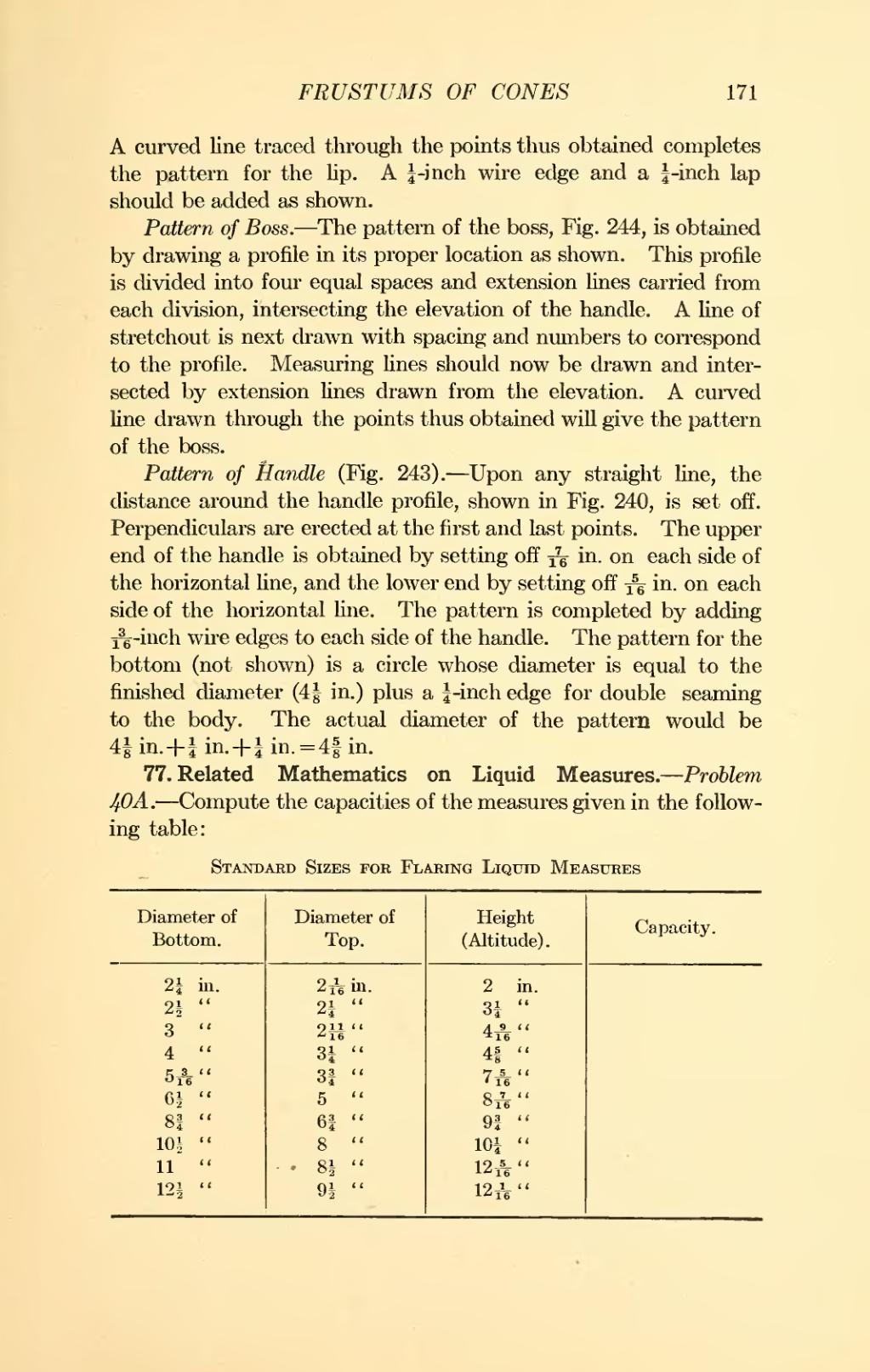
77. Related Mathematics on Liquid Measures.—Problem 40A.—Compute the capacities of the measures given in the following table:
| Diameter of Bottom | Diameter of Top. | Height. (Altitude). |
Capacity. | ||||
|---|---|---|---|---|---|---|---|
| 2¼ | in. | in. | 2 | in. | |||
| 2½ | '' | 2¼ | '' | 3¼ | '' | ||
| 3 | '' | '' | '' | ||||
| 4 | '' | 3¼ | '' | 4⅝ | '' | ||
| '' | 3¾ | '' | '' | ||||
| 6½ | '' | 5 | '' | '' | |||
| 8¾ | '' | 6¾ | '' | 9¾ | '' | ||
| 10½ | '' | 8 | '' | 10¼ | '' | ||
| 11 | '' | 8½ | '' | '' | |||
| 12½ | '' | 9½ | '' | '' | |||


